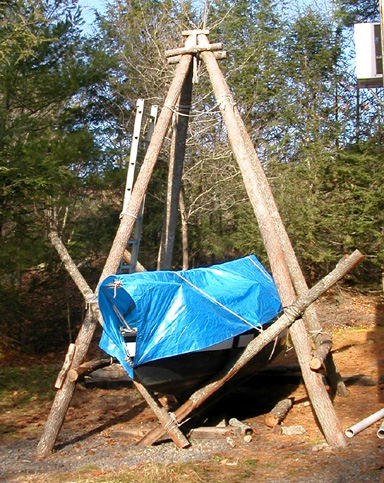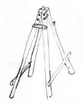
In the spring of 2004 I decided to build a gantry to hoist my sailboat, a Victoria 18, up off her trailer to give me free access to her bottom for painting. Victoria is equipped with a hoisting ring, solidly attached to her weighted keel, which can be accessed through a panel in the floor of the cabin. My idea was to build a four-legged tripod, or quadrupod, with legs equally spaced in all directions, to straddle Victoria, with the peak located vertically above the hoisting ring. Here is my original sketch of the concept as it first appeared in my mind.

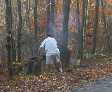
There is a dirt road behind my house running through the woods. On the side of that road I found four tall straight trees, of a diameter of 7 inches at the base, tapering to about 5 inches 20 feet up. They were dead, but still standing, so I felt little guilt felling them. Then, with my friends Andy and Dan, we went out with a chain saw and cut them down one by one.
tied one end to the trailer hitch of my car, (using, of course, the ol' timber hitch!)
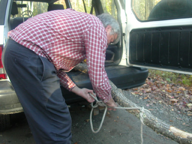
and dragged them back to my place.
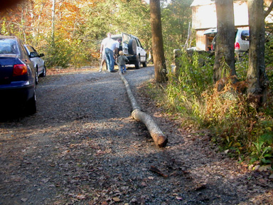
Next, out with the old fashioned tools—bow saw and axe, for some good old fashioned craftsmanship!
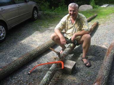
Next, we cut the pieces to length, and laid them out in the "A" configuration, with the fat ends of the side timbers at the bottom, tapering upwards, and the thinnest sections used for the crossbeam.
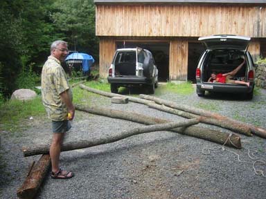
Then for some fine carpentry using the axe, to make the mating surfaces flat. We drilled holes for half inch steel lag screws of 6 or 8 inches, with which we secured the cross-beam to the A. We used two lag screws at each joint.
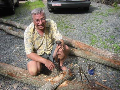
Next we sawed through both timbers at the peak of the A, to make a miter joint at 40°.
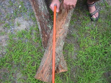
Then we chopped two steps at 5 and 7 inches, and bored through-holes for half inch diameter bolts and nuts of 6 and 8 inches respectively, to secure the peak.
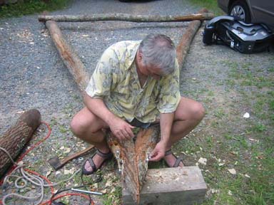
Here is the first completed A-frame, with Victoria on her trailer in the background.
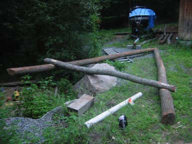
My friend Andy and I together could just barely move one A-frame a foot or two with each heave. Here is a handy technique for dragging an A-frame into position, which can be done single-handed. I use the shorter timber, with a rope tied near its top, as a lever to pull the peak of the A-frame up and forward in short steps, moving the base of the timber forward before each step. (The sloping rope in the background is not connected to the timber)
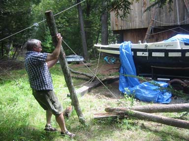
We raised up one A-frame and leaned it against the side of the house. There's Cap'n Andy on the 'Effing A!
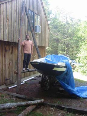
Andy clambered up, using "foot ropes" (secured to the timbers with constrictor knots) to secure a "Handy Billy" (block-and-tackle rig) to the peak of the A. We also dug small holes to secure the feet of the A-frame, 3 or 4 inches deep.
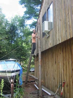
Then we secured a line from the peak of the A, through a block secured to a tall tree behind the house, and back down to belay on the small tree astern of Victoria. We then very carefully eased the A-frame over to a 20° angle and belayed securely.
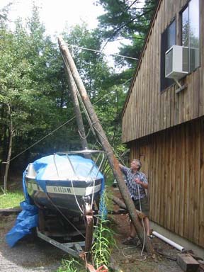
Then we hauled the second A-frame into position, and attached the peaks of the two A-frames together with the Handy Billy, to help haul her up to the vertical. (Note one tiny screw-up in the plan: the second A is lying upside-down, with its cross-beam on top of, instead of below the sides of the A, as in the original plan. This error went un-noticed.)
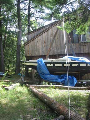
Next came the most dangerous and challenging part of the assembly. Slowly in stages, we raised the peak of the A, while hauling on the handy billy (whose fall line is seen belayed to the left side of the A), and backing up with a short timber to make sure the A-frame did not collapse back down on us. After each pull we braced up and took a rest before hauling again. It was like a good old-fashioned barn raising!
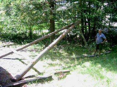
Finally, after much heaving and hauling, the second A went up and leaned against the first one. Note that they did not meet exactly peak-to-peak. However that was easy to fine-tune after the fact by moving the legs of the A's back and forth, and digging or filling the holes in which they stood.
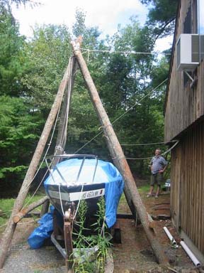
The gantry at this point was a little shakey and dangerous, so it was with some trepidation that I clambered up to tie an emergency lashing (with frapping turns) to hold the two peaks together. Only after this lashing was secure could I breath a sigh of releif. (Note how the peaks are now almost perfectly aligned.)
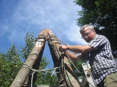
I then secured a second lashing lower down, just to make sure.
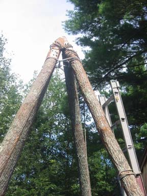
Finally, out of an abundance of caution, before I would risk my life clambering about up there, I rigged preventer braces on both A-frames to support them independent of each other.
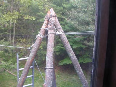
Next I sawed off the peak of the two peaks flush above the upper bolts. Then I inserted a car jack between the two peaks, and jacked them apart, so that I could chop their mating faces flat and smooth with the axe, before removing the jack and easing the lines to bring them together again. In retrospect it would have been a lot easier to do this fine-tuning down on the ground, with the A-frames lying on their sides before we erected them.
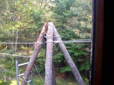
Then I fabricated two cross-arms, or trestle-trees with the axe,
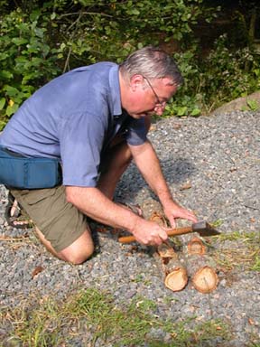
trimmed the peak timbers to shape just below the bolts with the axe,
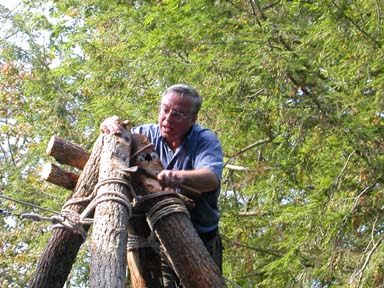
and secured the trestle-trees to the gantry using half-inch diameter lag screws of four inch length. Note the circle of foot ropes used to gain easy access to the peak.
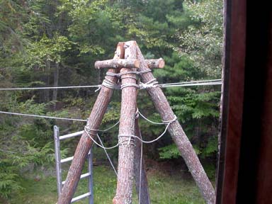
Next I fabricated a gantry cap out of a length of log, sawed in half lengthwise, with one flat and one curved surface. I laid it flat-side-down on top of the gantry and traced the outline of the top of the gantry on its underside. Then I carved out the part inside the outline with a chisel to a depth of about a quarter inch, to make it sit secure in its proper place.
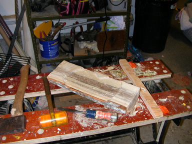
Then I secured it to the gantry head with two half-inch lag screws of four inches length.
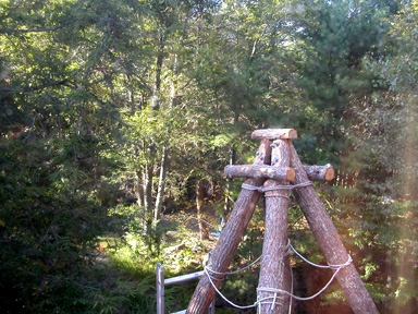
Finally I looped a rope over the gantry cap four times, and tied its ends with a sheet bend, then I hooked a block-and-tackle through the four loops.
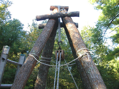
The gantry is now complete, ready to raise the boat!
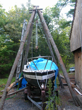
Victoria's displacement is listed at 1200 lbs. I ordered two triple blocks from McMaster-Carr part # 3146 T64, Wood Shell Block for Fibrous Rope, 1/2" rope, rated for 1800 lbs. I also happen to own an old fashioned "handy billy" with one single and one double block.
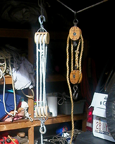
The load on the rope can be calculated by dividing the total load by the number of ropes between the two blocks. A triple-purchase, or three-fold tackle (Pronounced Tay-kle by those with salty tongues) has six ropes going between the two blocks, so the load is divided equally among them, thus each rope holds 1/6th of the load, 1200 lbs ÷ 6 = 200 lbs.
But this optimum pull can only be achieved when pulling the "fall line" upwards, where your final direction of pull contributes to the lifting of the load; known as rove "to advantage". This however would require us to be hauling the fall line from the top of the gantry, a most inconvenient location for a heavy haul. Therefore we rove the three-fold tackle to disadvantage, as shown at the right, below, hauling downwards from below, where the final shiv serves only to reverse the direction of pull, rather than to help lift the load.
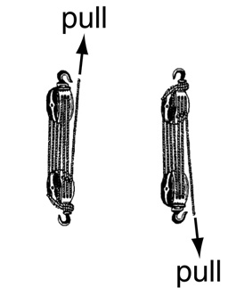
Used in this configuration the three-fold tackle divides the load equally among 5 ropes, 1200 lbs ÷ 5 = 240 lbs. That should be managable for two or three men hauling on the line. I purchased 100 feet of 1/2 inch diameter twisted nylon rope from McMaster-Carr Part # 3827 T514, rated at 582 lbs, with breaking strength at 6,400 lbs. That should be plenty with strength to spare!
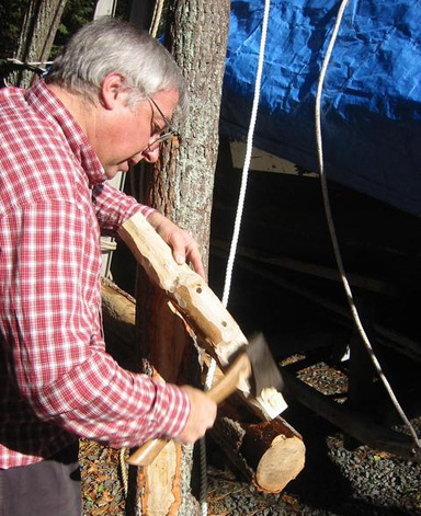
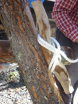
I fashioned a rough-hewn cleat out of a piece of scrap timber, and bolted it on to the A-frame with two half-inch lag screws of 6 inch length.
|
|
Then Dan and Andy started hoisting in traditional nautical fashion, Andy hauling, and Dan "tailing on" (or "tallying on"). Andy would take a hard pull, getting extra leverage by pulling the rope out like a giant bow. Then he would ease the strain for an instant, as Dan took up the slack to secure the pull gained. In this fashion we were able to raise the boat maybe three inches with each pull, but it was a very heavy haul.
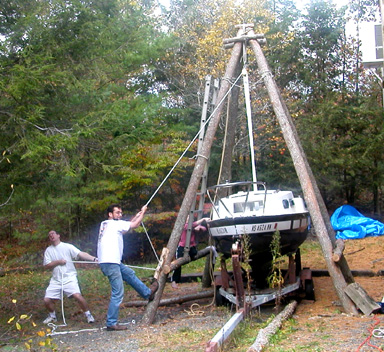
So we decided to rig the handy billy on to the fall line of the triple purchase tackle, hooking the hook of the handy billy into the loop of a bowline-on-a-bight tied into the larger fall line. The handy billy has four lines, counting the fall line, when rove to advantage, as shown below, i.e. our downward pull on the fall line of the handy billy contributes to the downward pull of the larger fall line of the triple purchase tackle. This reduces the 240 lbs of the larger fall line to 240 ÷ 4 = 60 lbs, which Dan could easily manage by himself.
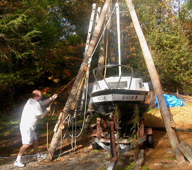
We raised her clear up off the trailer, pulled the trailer out from under her, and lowered her back down on to a line of blocks. She was a tad "down by the stern" while hanging on her ring, but could be easily leveled by lifting the stern.
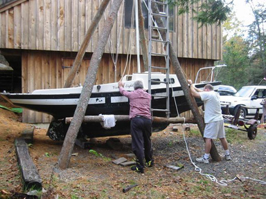
Next we constructed a cradle to hold Victoria upright. We lashed pairs of spars into "V" shape, and lashed them to the gantry, bow and stern.
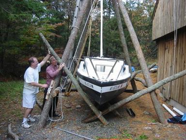
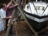
Here is the finished cradle. The boat sits lower in the cradle than on the trailer, it is easier to climb in and out of, with the help of the gantry.
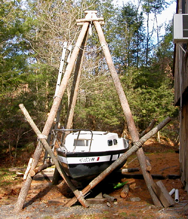
Finally we installed the winter tarp frame...
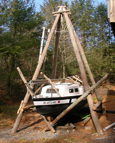
and the winter tarp for winter storage.
