Plato's Cave: The Full BCS
The Boundary Contour System (BCS) Model
The Boundary Contour System is a dynamic neural network model composed
of
shunting neurons
designed to replicate the properites of illusory contour formation as
observed in psychophysical studies. The figure below illustrates the
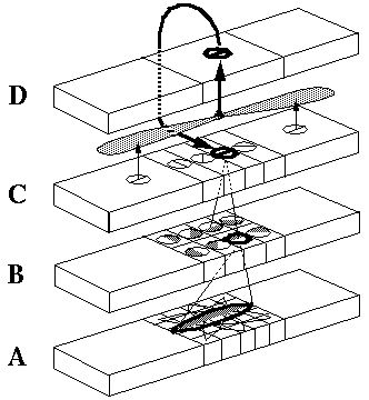
basic architecture of the BCS. The cells at A
represent a layer of light sensitive cells such as the ganglion cells
from the retina. The cells at B represent cortical
simple cells that receive input from the ganglion cells through
oriented receptive fields, so that different cells at
B respond to edges of different orientations at
A. For example the horizontal dark/light cell at
B, highlighted in the figure, receives input from the
highlighted elliptical region in layer A, excitatory
from the light half and inhibitory from the shaded half. All of the
cells depicted at B receive input from the same
spatial location at A through overlapping receptive
fields at different orientations. The cells in layer
C receive input from pairs of cells in layer
B which represent edges that are parallel in
orientation but of opposite direction of contrast. For example the
highlighted cell at C receives input from the
horizontal dark/ light and the horizontal light/dark cells at
B, producing an oriented representation that is
independent of direction of contrast. The three big blocks at each
layer represent three horizontally adjacent locations in the visual
field.

A principal feature of the BCS model is its ability to perform
boundary completion between oriented edges that are approximately
aligned, like the inducers of the Kanizsa figures which produce
illusory boundaries. The mechanism responsible for this boundary
completion is a layer of cooperative cells depicted in
D which receives input from layer C
through large, bipolar
cooperative receptive fields.
Like the receptive
fields of layer B, these bipolar receptive fields
occur at every orientation at each spatial location, but unlike those
fields the cooperative cell receptive field spans many spatial
locations (although only two are shown in the figure) in a direction
parallel to the orientation of the inputs preferred by the cooperative
cell. For example, the horizontal cooperative cell depicted in the
figure has a receptive field that is horizontally aligned to receive
input from layer C horizontal cells at horizontally
adjacent locations.
Return to argument
Return to Steve Lehar

